
 Reply With Quote
I've never had a problem like that before, try the megasquirt forums, someone there will know.


^^^ worked out how to test it at 0rpm in spark b test mode in megatune.
I got my boost control sorted - for some reason using MS-II Extra i fannyed around for ages until i accidentally realised the boost control was outputting on
the idle control wire (pin 30) instead of pin 3 (spr1) like i wanted it to?
Im not bothered if it works like that because i will not be using idle control at all. But it seems that whichever boost control pin i select (IAC1, IAC2, JS11, FIdle) it makes no difference, and the boost control still outputs on the idle control wire?


I've never had a problem like that before, try the megasquirt forums, someone there will know.
Project Thread
---> Add Your Puntos Here Please <---
http://www.torquestats.com/hall_of_fame/Fiat/Punto+GT
are you still running MS1? It looks like MS1 has correctly labelled boost control pins, but with MS2 i dont have an option for JS2.... I realised that to change pin i had to restart the ecu each time. Now i only get any output at all on the Fidle pin. IAC1, 2 and JS11 arent hooked up to anything anyways.
and the MSextra forums are very slow! i posted up last night but need my post approved by a mod still, but theres hardly any active users anyways
ah, now been told that i should have jumpered S12C to JS11 for a diode feed in. How comes this wasnt on your diagram pete? cos you should have had to do this for MS1 as well?
i see now that you would have had to do it as per idle control instructions anyways. My bad.
I did have a think about it but I built mine that long ago I can't remember now.
Project Thread
---> Add Your Puntos Here Please <---
http://www.torquestats.com/hall_of_fame/Fiat/Punto+GT
Ok some extra information for anyone having problems with the VR circuit on megasquirt.
A few modifications have been shown to help with tach triggering issues:
1. If you experience tach drop-outs at higher rpms when using the VR input circuit, you might need to replace the diode D24. The issue is with the reverse recovery time of a 1N4001, its in the 30µsec region. You can use a 1N4148 diode (1N4148DICT-ND from Digi-Key) which is much faster and should solve this problem. This became the 'standard build configuration' in October of 2008.
2. You can remove the capacitor C32. This is the capacitor in parallel with R47. Although removing this capacitor may cause a ever-so slight phase shift, it will probably not be noticeable.
3. You can use a 0.001µF capacitor in C31 (instead of a 0.1µF capacitor) which may help with high frequency signals (such as high tooth count wheels). Many later kits (post-October 2008) come with a 0.001µF capacitor as standard.
Make sure that your crank trigger is right! use the tooth logger, you should only get one spike for each turn of the trigger wheel.
Myself I removed the capacitors C31 and C32 and it cured all the holding back and missfire problems, i'm going to try a 0.001 capaciter in C31 and see what happens. (Turns out I already had a 0.001 capacitor in place of C1, I put this back and it still runs well with this and with no cap in C2)
Or buy a VR conditioning board such as:
http://www.diyautotune.com/catalog/z...ers-p-378.html
http://forum.jbperf.com/viewtopic.php?f=6&t=78
VR conditioning circuits are available on ebay usually.
Project Thread
---> Add Your Puntos Here Please <---
http://www.torquestats.com/hall_of_fame/Fiat/Punto+GT
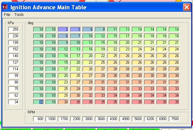
This is my current timing map, all the base values up to atmospheric come from Uno turbo timing maps, up into boost I removed .75 degree of timing per PSI of boost.
My car runs well on this map but it does need some more fine tuning.
Project Thread
---> Add Your Puntos Here Please <---
http://www.torquestats.com/hall_of_fame/Fiat/Punto+GT
hey pete did you time yours with a timing light? Im just wondering how important this is, thats all.
Being MS-II i only need the angle for first tooth BTDC, which i have set as a good initial figure that others have used for FIRE engines, and i have a very rough map yet which idles ok and revs a little, but i know i need a load more advance for it to rev right.
IF its needed, i wont bother playing with it any more and i'l get it timed to perfection, but i was thinking, why not just leave the trigger angle where it is and alter it all through the spark table?
 Posting Permissions