
 Reply With Quote
Originally Posted by charlieboy
I have made a few stupid mistakes which cost me hours of time,Now i've made them no one else will have to.
8 hours roughly from start to finish if it all goes smoothly.


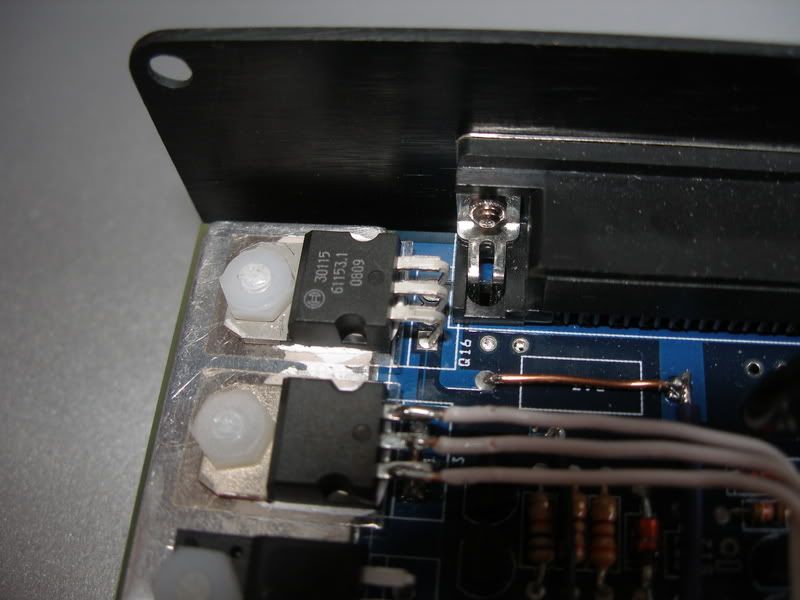
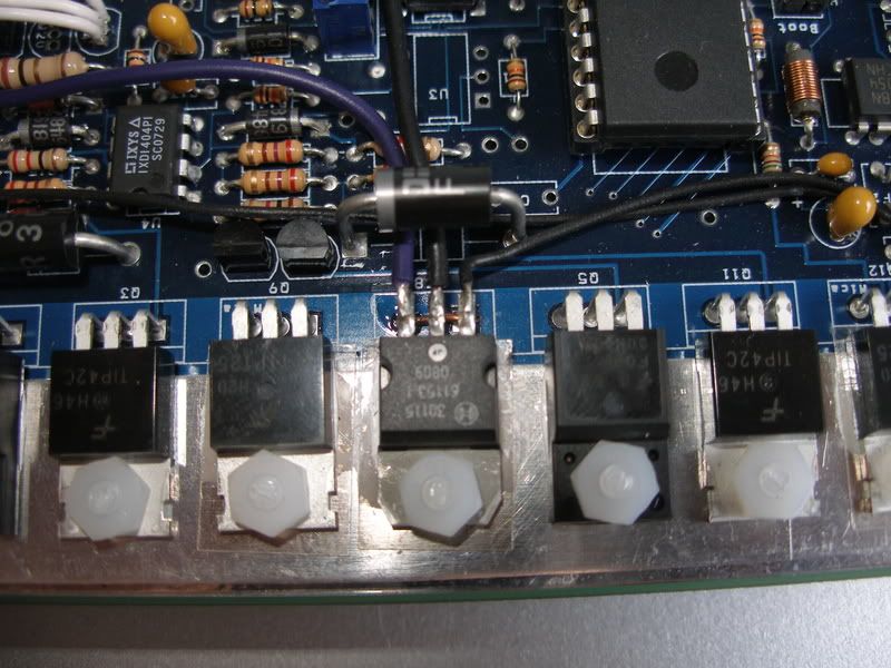
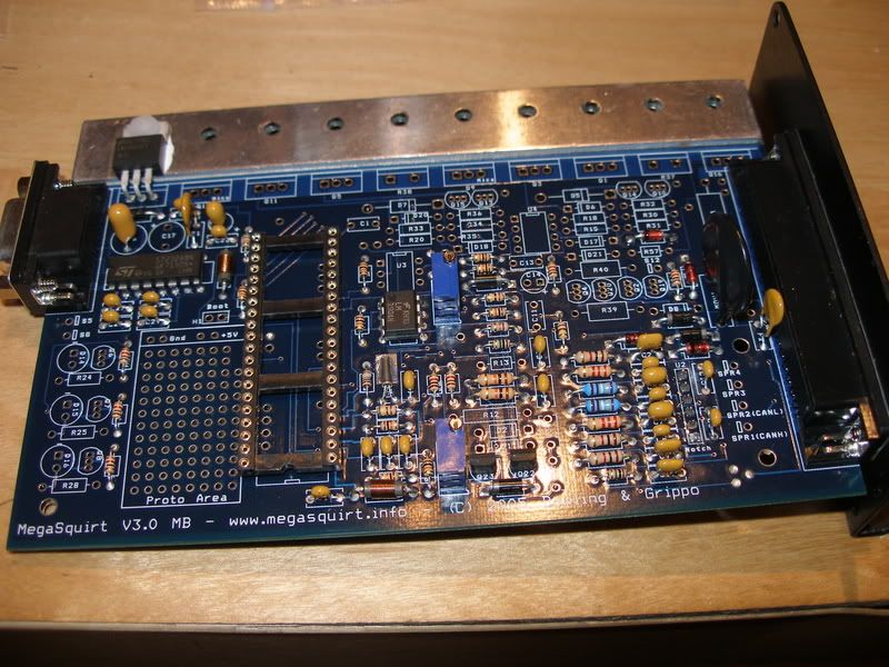
Tonight I started working on the output section. Heres a couple of decent pictures of so far.
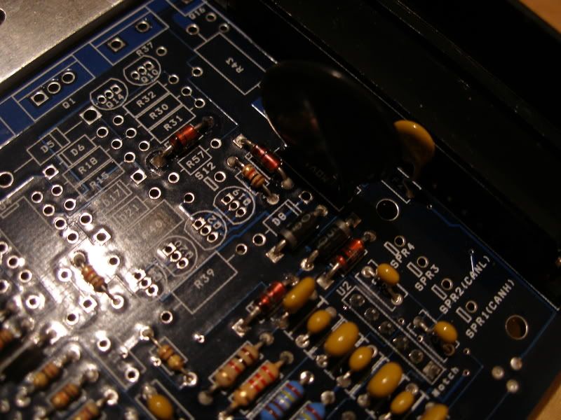
I started at step 56, when you get to step 59 Do not install D8 in the center of the picture, Due to running a PWM idle control valve.
When you reach Step 62 do not install Q4 Idle control transistor as this cannot handle the bosch idle control valve, This Transistor is replaced by the one in the PWM idle Mod kit.
I found I could mount the PWM transistor in the R37 location on the heatsink bar. Follow the insructions for PWM users below step 62. Solder the supplied wires from Q4 to the upgraded transistor. Remember not to install Q20 and D8.
Jumper R39 with wire instead of fitting the resistor.
Remember step 63 and 64
Thats the PWM Idle control finished. This took me a while to work out as I was a bit confused but it all made sense in the end
Step 65
Now is where it gets hard, Well I did for me as I was very confused with the coil driving circuits that come next.
The way we wish to drive the coils/engine is called wasted spark. (Same as the way the coils are originally triggered)
Wasted Spark: This is used on a lot of 4 stroke engines and is where a pair of cylinders are fired together, one cylinder is on the compression stroke and the other on the exhaust stroke. The 2 cylinders that are fired are the pair that move together and are therefore opposite each other in the firing order. This setup therefore has multiple coils, usually 2 for a 4cy, 4 for a 8cy, etc. It does NOT have a distributor, as the spark plugs in the cylinders are connected directly to the coils.
E.g.
Fiat 4 cylinder firing order = 1, 3, 4, 2 This would be 2 rotations of the crank, so 720 degs.
To fire this engine in wasted spark we would fire 1+4 together (as these are opposite in the firing order), then 180deg later we would fire 3+2 (again these are opposite in the firing order), this repeats every crank revolution.
The cylinder that is fired on it's exhaust stroke is know as the "wasted spark" as it produces no power. The benefits are that the coil fires less often than when using a single coil and has more time to charge ready for its next spark. This is very helpful at high revs when the charge time can be very small.
The fiat coil pack as far as I know is 4 coils, now to use this we need two coil drivers, one to fire a pair of coils for 1+4 and then another driver to fire the second pair of coils for 2+3 (Looking at the wiring diagrams today the coil pack is 2 coils, one for 1+2 and one for 2+3)
To build this section I used a link I was sent by DIY Autotune. I had to email them as I got totally lost, everything I'm typing now I learned last night, Lol.
This Is the link
http://www.msextra.com/manuals/MS_Ex...nual.htm#2coil
I have detailed what I did in my next post.
Project Thread
---> Add Your Puntos Here Please <---
http://www.torquestats.com/hall_of_fame/Fiat/Punto+GT
I have made a few stupid mistakes which cost me hours of time,
8 hours roughly from start to finish if it all goes smoothly.
Project Thread
---> Add Your Puntos Here Please <---
http://www.torquestats.com/hall_of_fame/Fiat/Punto+GT
Thats right, controling the bosch valve with a PWM idle control mod kit.
http://www.diyautotune.com/catalog/p...t39-p-134.html
Project Thread
---> Add Your Puntos Here Please <---
http://www.torquestats.com/hall_of_fame/Fiat/Punto+GT
Coil drivers:
Jumper the connections of R37 together and then do the same with R38 as this is easier now than later on.
Start building the first coil driver.
http://www.msextra.com/manuals/MS_Ex...htm#singlecoil
Install your first ignition driver fet in position Q16
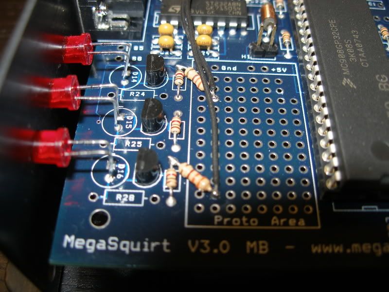
Solder your first 330ohm resistor between the top of R26 and the proto area.
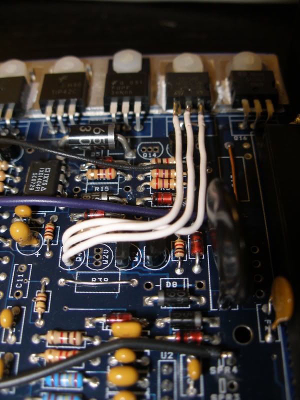
Link from the resistor with a wire to IGBTIN on the top right of the board (Just under the white wires in the picture below). This will form a connection to pin 1 of the ignition driver fet fitted in position Q16.
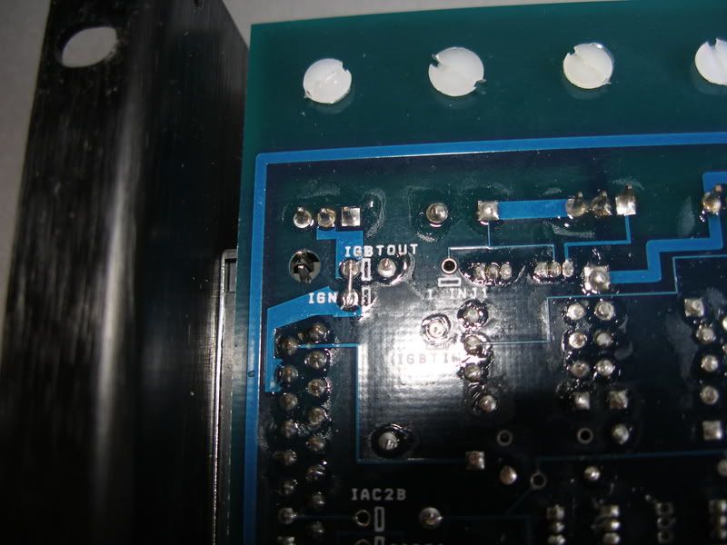
Link IGBOUT to IGN on the other side of the board
Make sure R57 is removed.
First output done!
Then go on with the second output.
http://www.msextra.com/manuals/MS_Ex...nual.htm#2coil
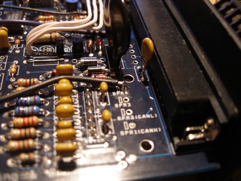
Fit your second coil driver fet into position R38
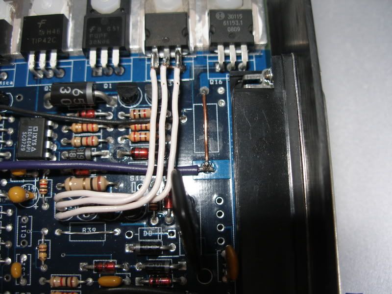
Solder your second 330ohm resistor to the top of R29 and the proto area then solder a link wire from the end of the resistor to the first pin of your second fet.
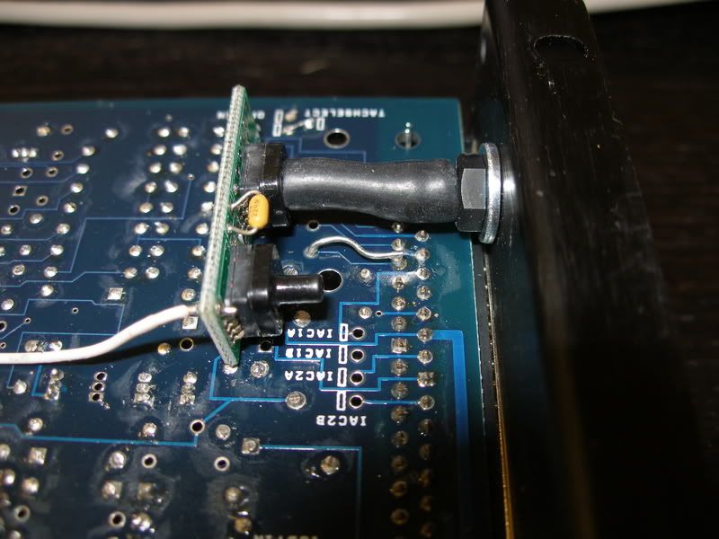
Solder a thick wire from SPR4 directly to the loom connector as the circuit board trace cannot take the current of driving a coil directly. Its best to make the wire stick right through SPR4 so you can connect directly to it on the other side.
Solder a wire from pin 2 of the second ignition driver fet to SPR4
Solder a copper link wire in place of R43 and make sure to remove R57 if it is fitted
Link pin 3 of the second driver fet to the copper link wire fitted in the place of R43 as in the picture above
Now you have a coil driver (Spark A) outputting on pin 36 of your loom connector and a second coil driver (Spark B) outputting on pin 6 (SPR4) of the loom connector.
Project Thread
---> Add Your Puntos Here Please <---
http://www.torquestats.com/hall_of_fame/Fiat/Punto+GT
Next complete steps 66 to 80 remembering the following:
Step 71, You cannot do this as R37 and R38 have been jumpered
Step 74, Do not install Q20
Step 75, Fit a jumper in place of R39
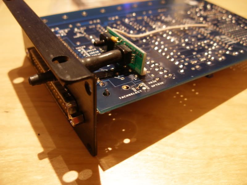
Step 76, The cases are already cut out so you can just fit the end plate and complete step 80.
Thats the ecu finished
Now to install the MS1-Extra firmware.
Last edited by DR_EVIL; 6th October 2011 at 16:42.
Project Thread
---> Add Your Puntos Here Please <---
http://www.torquestats.com/hall_of_fame/Fiat/Punto+GT
Am I right in thinking that the GT2 & GT3 looms will be the same pin outs?
Just had a quick look, pin outs are the same.
Project Thread
---> Add Your Puntos Here Please <---
http://www.torquestats.com/hall_of_fame/Fiat/Punto+GT

I think 60deg is value for trigger offset settings, but i never try it (i run MS2Extra from beginning)
I just drove a couple miles in a GT running megasquirtNot my main GT just my runaround one, Not done any tuning yet apart from richening it up enough that it will rev well.
Last edited by DR_EVIL; 6th October 2011 at 16:43.
Project Thread
---> Add Your Puntos Here Please <---
http://www.torquestats.com/hall_of_fame/Fiat/Punto+GT
Just ordered mine with a Innovate LC-1 Digital Wideband.
£287.429 delivered. Will be here in 5 days!
Adi
 Posting Permissions