Page 1 of 30 12345611 ... LastLast
Results 1 to 10 of 299

Thread: Building a MS1 ecu for a Punto GT

  1. #1
    PSC Trader DR_EVIL's Avatar
    Join Date
    Jul 2003
    Location
    Middlesbrough
    Posts
    3,385

    Building a MS1 ecu for a Punto GT

    I hope this will help more punto owners to have a go with this very interesting ecu. Some of the features are amazing.

    I'm going to attempt to get a running car at the end.

    I have never built anything like this before also I have never tuned a car before so this could be a very long project.
    Last edited by DR_EVIL; 6th October 2011 at 17:34.

  2. #2
    PSC Trader DR_EVIL's Avatar
    Join Date
    Jul 2003
    Location
    Middlesbrough
    Posts
    3,385
    Here is the link to the assembly manual

    http://www.megamanual.com/ms2/V3assemble.htm

    Follow this carefully and there isn't much that can go wrong, also there is lots of forum help available if it does.

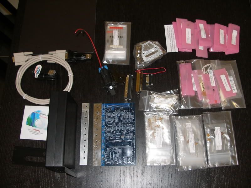
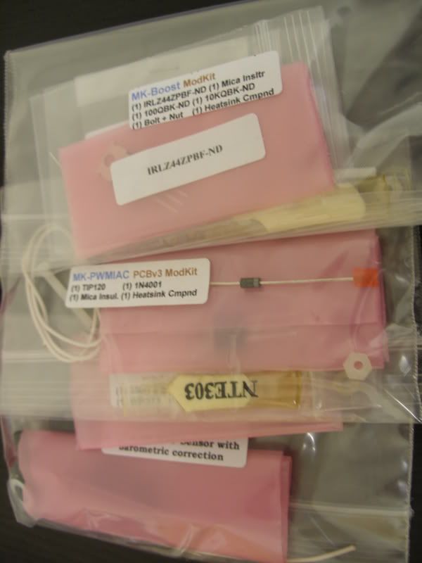
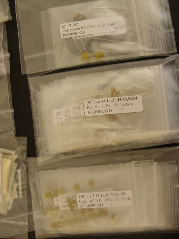
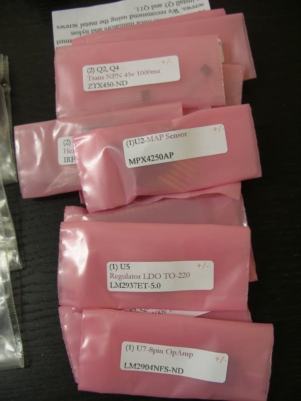
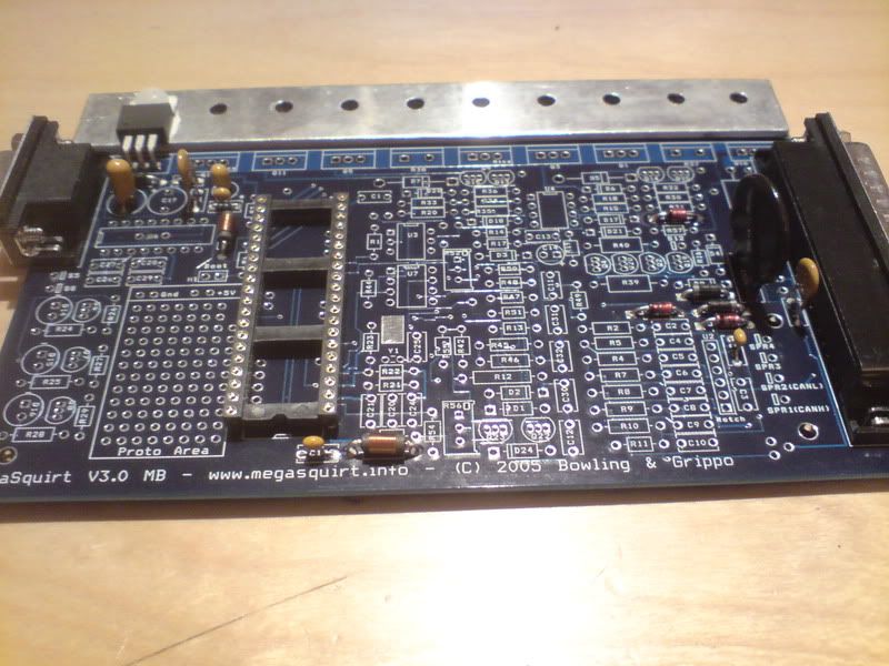
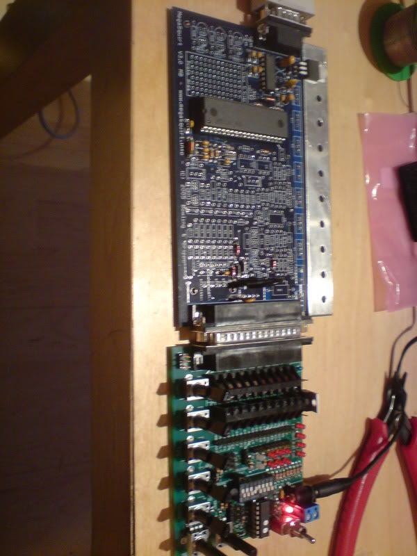
    Heres the kit laid out, everything is labled neatly and packed in bags, The pink bags are static sensitive so ground yourself before taking any component out of them.


    I suggest you print out the componant map, it will come in useful
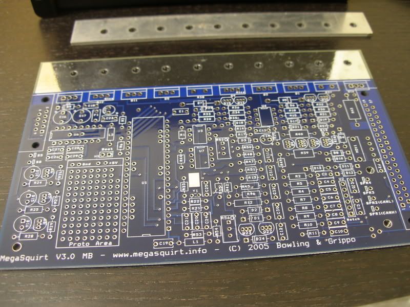
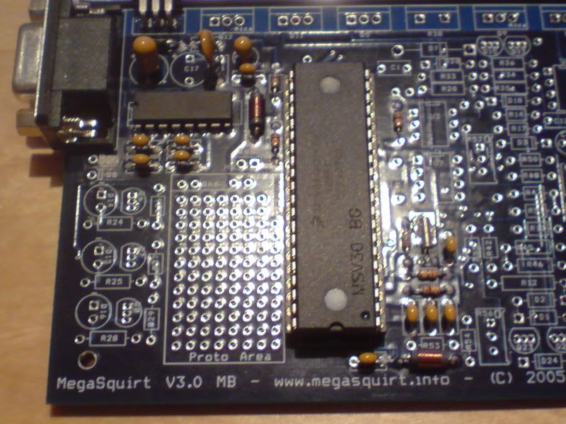
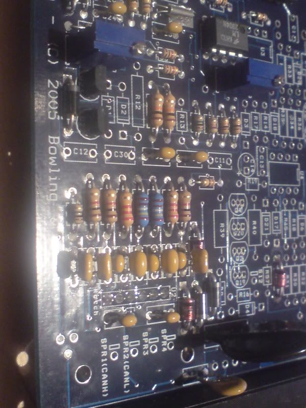
    Step 1

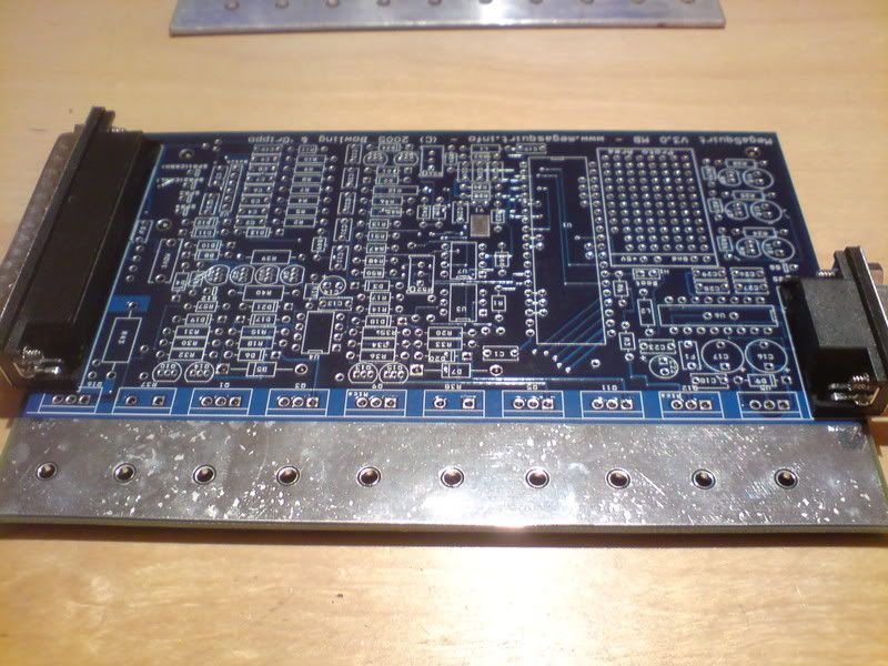
    First I soldered on the connectors


    Then the power supply components


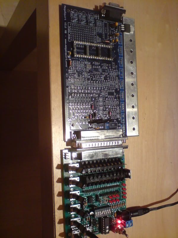
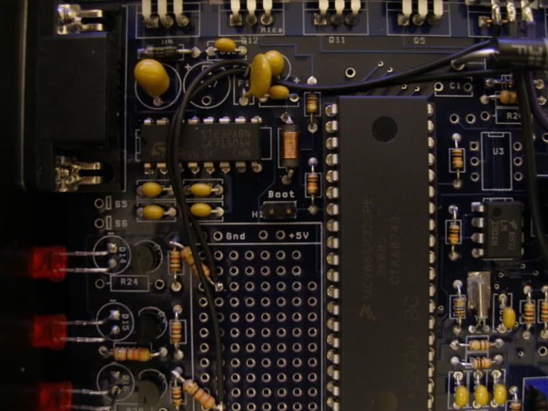
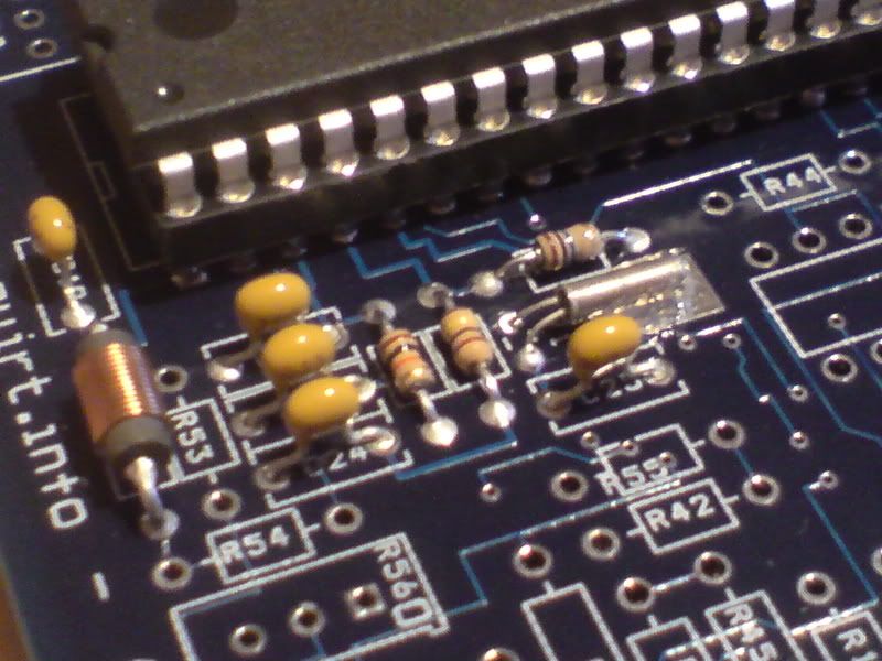
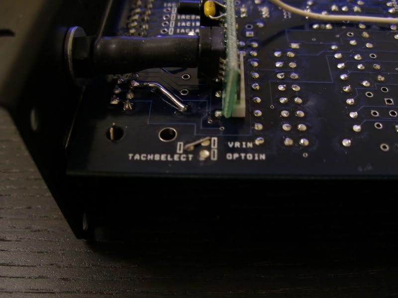
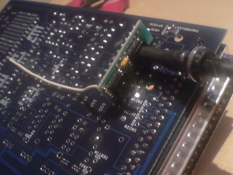
    When you get to step 19, Personally I installed pins here on the boot header as we need to load the processer with ms1 extra code later on. (I added this picture so ignore all the new bits)


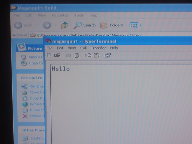
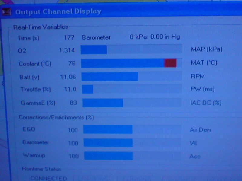
    This took an hour or so, then I hooked up the stimulator to supply 12 volts and tested the voltages at pins on the processer socket to make sure that the power supply circuits were functioning (Step 23).

    All checked out and awaiting more building.

    Last edited by DR_EVIL; 6th October 2011 at 17:35.

  3. #3
    PSC Trader DR_EVIL's Avatar
    Join Date
    Jul 2003
    Location
    Middlesbrough
    Posts
    3,385
    Next I built the communication section (Starting step 24). First four capacitors and a microchip are soldered onto the main board.


    Next the communication cable and then the communication components on the megasquirt board are tested. Two pins on the processor socket are bridged and a program called hyperterminal is used to send data through the tuning cable, this is bounced back to the computer through the bridged pins and show the communications are working properly.


    Last edited by DR_EVIL; 6th October 2011 at 17:36.

  4. #4
    PSC Trader DR_EVIL's Avatar
    Join Date
    Jul 2003
    Location
    Middlesbrough
    Posts
    3,385
    Ok tonight I started on the clock circuit (Step 27). It involves 5 or 6 capacitors a few resistors, fitting the timing crystal and putting in the processor for the first time.


    Next the ecu is connected to the pc to test the clock circuit and communications.


    On the top left is the timer which should count up in seconds, also the battery voltage is displayed, all the rest show random rubbish at this stage.


    I'm pleased with it now, feels like i'm getting somewhere!

  5. #5
    Section Mod Debo's Avatar
    Join Date
    Jun 2004
    Location
    Manchester
    Posts
    5,912
    Who maps Mega Squirt in the UK Peter?

    This is something for other people to consider - if they bought it, how far would they have to travel to get it mapped/re-mapped, tweaked etc.
    If you have any car care related questions, ask me in the Cleaning/Detailing section.

  6. #6
    PSC Trader DR_EVIL's Avatar
    Join Date
    Jul 2003
    Location
    Middlesbrough
    Posts
    3,385
    Well using all the guides available pretty much anyone with some common sense and intelligence can get a well running car.

    For the fine tuning it is mapped in generally the same way as other standalone so most people that map dta/haltech etc should have no problems.

    Motorscope in Northallerton said they would map it and also I have a friend who runs a tuning company down the road from me who will do mapping.

  7. #7
    PSC Trader DR_EVIL's Avatar
    Join Date
    Jul 2003
    Location
    Middlesbrough
    Posts
    3,385
    Next I started on the input section. (step 42)

    When I got to step 50, the tach signal input, I skipped the hall/optical part and went right to the VR section (step 51)
    The GT uses a VR sensor, the hall part is not needed.


    Step 52 you must install jumper wires to select the trigger type.


    I selected VROut

    The map sensor part was different from standard as I have the upgraded map sensor so I went over to this link and followed all the instructions

    http://www.diyautotune.com/catalog/m...ion-p-117.html


    After the map sensor is fitted dont forget to complete step 54, that is the input section done.

    I connected everything back up to the pc and all inputs were working fine.
    Last edited by DR_EVIL; 6th October 2011 at 17:37.

  8. #8
    PSC Trader DR_EVIL's Avatar
    Join Date
    Jul 2003
    Location
    Middlesbrough
    Posts
    3,385
    Ok anyone wanting one of these supplied built with the same modifications as the one i'm building, Adi has found out the price.

    This is from http://diyautotune.com/

    Here is what it would cost to have a V3.0 built with those mods.
    MS130-C $329 Assembled Megasquirt-I with V3.0 PCB
    MOD_x30PWMIAC: PWM IAC Modkit Installation $22
    MOD_130IGN2: Dual Ignition Outputs through BIP373 coil drivers $54
    MOD_MAPDaddy4 Installed $65
    SM-wirebund 23" Long wire bundle. 12
    TuneCable $5.50 6' DB9 tuning cable
    Subtotal--$487.50
    Shipping insurance--$6.50
    Shipping and handling--$41.50
    Total--$535.50

  9. #9
    PSC Trader DR_EVIL's Avatar
    Join Date
    Jul 2003
    Location
    Middlesbrough
    Posts
    3,385
    Originally I built this MS1 unit, after a year or more I upgraded it to an MS2 by changing the processor.

    Ms2-Extra caught up and improved on MS1-Extra eventually.
    Last edited by DR_EVIL; 6th October 2011 at 17:40.

  10. #10
    PSC Trader DR_EVIL's Avatar
    Join Date
    Jul 2003
    Location
    Middlesbrough
    Posts
    3,385
    Quote Originally Posted by munch8987
    do you know of any site where you can get the base maps for any car??

    my mates running megasquirt in his mk1 astra and we cant get the git to run
    Check that the IGN LED on MegaSquirt® (the LED closest the DB9 serial connector) flashes on and off as you crank the engine. If it doesn't, MegaSquirt® either:

    does not have power (possibly only while cranking - many automotive power feeds are disabled while cranking, make sure your 12 Volt feed
    stays 'hot'), or
    does not have a tach signal (assuming it worked on the stim).
    You need to check both of these conditions and fix which ever is not right.

    If you have been trying to start your engine for more than 15 to 20 minutes, you ought to investigate other sources of problems before continuing to try to start the engine.

    Did he buy it built or build it?

    Have you followed all the "Starting your engine" section in the megamanual?

    You dont need much to get an idling engine, Just some fuel and a spark at the right time.

    You checked Fuel spark and timing?

Page 1 of 30 12345611 ... LastLast

Similar Threads

  1. Building the MS Stimulator
    By DR_EVIL in forum Dr Evil Stainless Exhausts & Tuning
    Replies: 0
    Last Post: 6th October 2011, 14:26
  2. Engine building
    By addzzp in forum Punto Chat
    Replies: 13
    Last Post: 20th November 2009, 20:51
  3. Building a sub box...
    By OMGWTF in forum I.C.E., Security and Electrical
    Replies: 12
    Last Post: 6th March 2008, 00:10
  4. And so it begins... BBQ Building
    By Puntoboy in forum Punto Images
    Replies: 65
    Last Post: 5th August 2007, 11:24
  5. building PC
    By shamster in forum Technobabble
    Replies: 30
    Last Post: 25th February 2005, 12:23

Posting Permissions

  • You may not post new threads
  • You may not post replies
  • You may not post attachments
  • You may not edit your posts
  •